
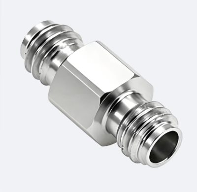
1.85 mm
precision coaxial connectors up to 67 GHz
1.85 mm precision connectors: 50 Ω, DC–67 GHz, VSWR 1.25, threaded coupling, −55 to +165 °C; 1.85-JFD flange-mount sockets for Ø0.23 and Ø0.30 mm pins, adapters to 1.0 and 2.4 mm.
| Characteristic impedance | 50 Ω |
|---|---|
| Frequency range | DC–67 GHz |
| VSWR | 1.25 (typical) |
| Insertion loss | ≤ 0.06·√f (GHz) dB |
| Insulation resistance | ≥ 5000 MΩ |
| Dielectric withstanding voltage | ≥ 500 V (RMS) |
| Body | passivated stainless steel; gold- and nickel-plated brass |
| Center conductor | beryllium copper; gold-plated brass |
| Insulator | PEI, PTFE |
| Coupling | threaded |
| Part number examples | 1.85-JFD9…12 (flange-mount sockets), 1.85M-1.85F, 1.85F-SSMPM (adapters) |
| Operating temperature | −55 to +165 °C |
About the series
Overview
The 1.85 mm series — high-precision millimeter-wave connectors with operating frequency up to 67 GHz and threaded coupling. Characteristic impedance 50 Ω, VSWR 1.25 (typical), insertion loss max 0.06·√f dB, insulation resistance at least 5000 MΩ, dielectric withstanding voltage 500 V, operating temperature −55 to +165 °C. Body — passivated stainless steel or gold- and nickel-plated brass, center conductor — beryllium copper or gold-plated brass, insulator — PEI, PTFE. The 1.85 mm interface also mates with 2.4 mm.
Versions
- Two-hole flange-mount sockets for Ø0.23 mm pins (1.85-JFD9, 1.85-JFD11) and Ø0.30 mm pins (1.85-JFD10, 1.85-JFD12).
- Cable plugs and sockets; adapters 1.85 ↔ 1.85 mm (VSWR < 1.3 up to 67 GHz), 1.85 ↔ SSMP and SMP (< 1.2–1.3 up to 40 GHz), 1.85 ↔ 2.4 mm (< 1.2 up to 50 GHz).
Applications
Test and measurement paths and vector network analyzers up to 67 GHz, millimeter-wave communications equipment.
Part numbers
Part numbers of this series are configured to order — send the required configuration through the quotation form.
Questions and answers
What are the specifications of A1-CONNECT 1.85 mm connectors?
50 Ω, DC–67 GHz, VSWR 1.25, insertion loss max 0.06·√f dB, insulation resistance at least 5000 MΩ, dielectric withstanding voltage 500 V, −55 to +165 °C.
Do 1.85 mm connectors mate with 2.4 mm?
Yes, the 1.85 and 2.4 mm interfaces are mechanically compatible; 1.85 ↔ 2.4 mm adapters with VSWR < 1.2 up to 50 GHz are also available.
What is the difference between 1.85-JFD9 and 1.85-JFD10?
The pin diameter the flange-mount socket is designed for: Ø0.23 mm for JFD9 and Ø0.30 mm for JFD10; JFD11/JFD12 are the same range with a different flange.